描边是很多NPR渲染中必不可少的一部分,主流的方案大致有三种:
- 多Pass绘制背面描边
- 后处理——基于深度、法线的边缘检测
- 基于网格的共享边计算倒角边(Silhouette Edge)来绘制"线"(实际绘制的是quad)
当然,需要注意的是,我们基于法线与视线方向的内积得到的像是描边的效果应该是边缘光(Rim Lighting),而不是描边(当然,作为fallback倒是可以的)。此外,如果是2D的描边,一般更多会用SDF来实现。
项目地址: RicciFloOow/Outline-Analysis: 三种主流描边方案
多Pass描边
实现原理
多Pass描边的原理就是将网格"外扩",然后计算"外扩"后的渲染结果与正常渲染结果的差集,该差集即为描边区域。由于NPR渲染的对象通常是前向渲染的,所以多Pass描边的方案并不会对渲染管线造成很大的影响。
对于球面、立方体这类简单的几何体,“外扩"似乎就是整体放大一些。不过我们只要考虑稍微复杂一点的几何体,比如环面,就能发现单纯的将比例放大是不合理的。因此,我们应该考虑几何体表面局部的信息,再结合"向外”(这种带方向的属性),很自然的能联想到该用法线来实现"外扩"。至于实现差集,我们通过绘制"外扩"后的背面(剔除正面),并绘制正常的正面(默认剔除背面),自然就能利用ZTest得到两者的差集(注意,除非特殊情况,否则我们不需要管这个两个Pass的顺序)。
于是,最简单的描边就是
 1
 2
 3
 4
 5
 6
 7
 8
 9
10
11
12
13
14
15
16
17
18
19
20
21
22
23
24
25
26
27
28
29
30
31
32
33
34
35
36
37
38
39
40
41
42
43
44
45
46
| SubShader
{
Pass
{
Cull Back
//正常渲染, 省略
}
Pass
{
Cull Front//实现差集的核心
CGPROGRAM
#pragma vertex vertOutline
#pragma fragment fragOutline
#include "UnityCG.cginc"
struct v2fBase
{
float4 vertex : SV_POSITION;
};
struct appdataBase
{
float4 vertex : POSITION;
float3 normal : NORMAL;
};
float _OutlineWidth;
half4 _OutlineColor;
v2fBase vertBase (appdataBase v)
{
float4 wPos = mul(unity_ObjectToWorld, float4(v.vertex.xyz + v.normal * _OutlineWidth, 1.0));
v2fBase o;
o.vertex = mul(UNITY_MATRIX_VP, wPos);
return o;
}
fixed4 fragOutline (v2fBase i) : SV_Target
{
return _OutlineColor;
}
ENDCG
}
}
|
但很显然,上面的方案在几何体非等比例拉伸的情况下就会出现明显失真了,于是我们自然的会去考虑在世界空间下外扩,即VS内的改为
1
2
3
4
5
6
7
8
9
| float4 wPos = mul(unity_ObjectToWorld, float4(v.vertex.xyz, 1.0));
float3x3 tW2OMat = (float3x3)transpose(unity_WorldToObject);
float3 normal = mul(tW2OMat, v.normal);//转到世界空间
//
wPos.xyz += normal * _OutlineWidth;
//
v2fBase o;
o.vertex = mul(UNITY_MATRIX_VP, wPos);
return o;
|
但是这样做仍然存在问题:在透视相机下,相同的的描边宽度(“外扩"距离)会出现近处粗而远处细的问题。那么解决这种问题的办法就是在裁剪空间中"外扩”。
 1
 2
 3
 4
 5
 6
 7
 8
 9
10
11
12
| v2fBase o;
float4 wPos = mul(unity_ObjectToWorld, float4(v.vertex.xyz, 1.0));
float4 clipPos = mul(UNITY_MATRIX_VP, wPos);
o.vertex = clipPos;
float3x3 tW2OMat = (float3x3)transpose(unity_WorldToObject);
float3 normal = mul((float3x3)UNITY_MATRIX_VP, mul(tW2OMat, v.normal));
//
float2 nOffset = normalize(normal.xy);
nOffset.x *= (_ScreenParams.y / _ScreenParams.x);
float2 offset = nOffset * _OutlineWidth / _ScreenParams.y * 2.0;
o.vertex.xy += offset * o.vertex.w; //
return o;
|
于是我们可以得到
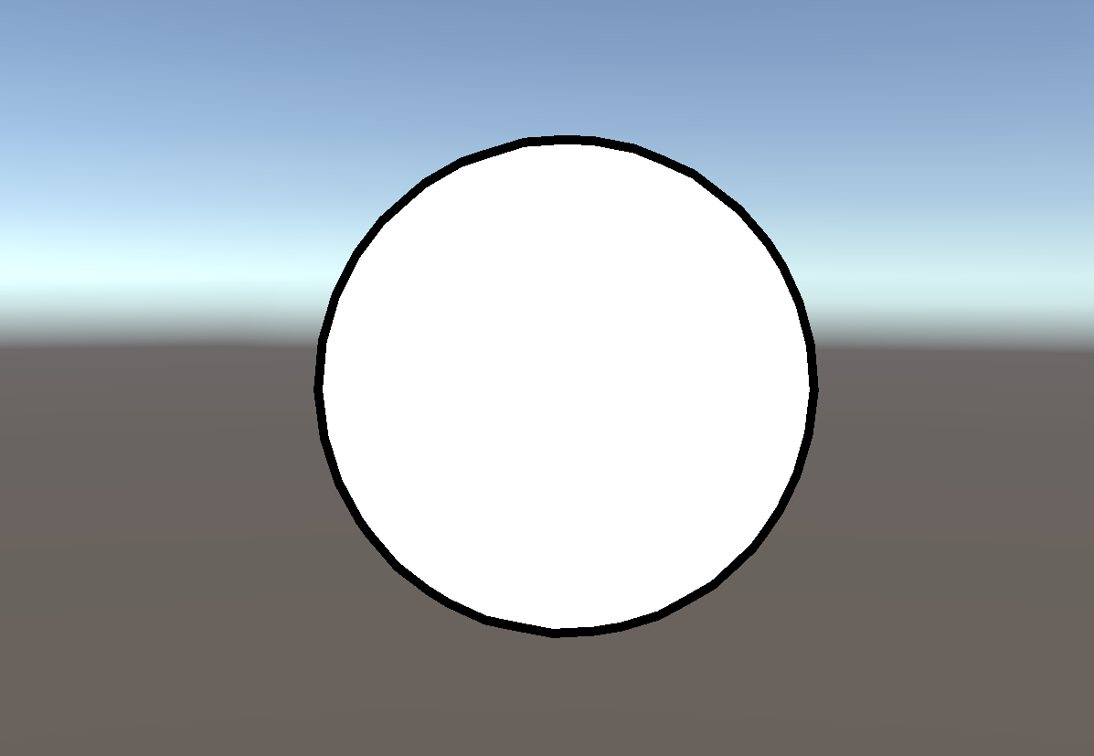
不过,当我们换个更简单的模型时就出现问题了
这是因为模型中存在位置相同,但是法线不同的顶点。
法线修复
既然法线不同,那么我们可以基于原有的法线,计算出一个位置相同的顶点共用的一个方向。最自然的就是无权重的平均法线。为了防止浮点精度或是本身模型制作的瑕疵,我们定义了如下顶点与边的结构
 1
 2
 3
 4
 5
 6
 7
 8
 9
10
11
12
13
14
15
16
17
18
19
20
21
22
23
24
25
26
27
28
29
30
31
32
33
34
35
36
37
38
39
40
41
42
43
44
45
46
47
48
49
50
51
52
53
54
55
| public struct GeoPoint : IEquatable<GeoPoint>
{
public Vector3 Pos;
private const float K_ToLerance = 1e-5f;
private const float K_SqrToLerance = K_ToLerance * K_ToLerance;
public GeoPoint(Vector3 pos)
{
Pos = pos;
}
public bool Equals(GeoPoint other)
{
return (Pos - other.Pos).magnitude < K_SqrToLerance;
}
public override bool Equals(object obj)
{
if (obj is GeoPoint)
{
return Equals((GeoPoint)obj);
}
return false;
}
public override int GetHashCode()
{
int x = Mathf.RoundToInt(Pos.x / K_ToLerance);
int y = Mathf.RoundToInt(Pos.y / K_ToLerance);
int z = Mathf.RoundToInt(Pos.z / K_ToLerance);
return x.GetHashCode() ^ y.GetHashCode() << 2 ^ z.GetHashCode() >> 2;
}
}
public struct GeoEdge : IEquatable<GeoEdge>
{
public GeoPoint v0;
public GeoPoint v1;
public GeoEdge(GeoPoint v0, GeoPoint v1)
{
this.v0 = v0;
this.v1 = v1;
}
public bool Equals(GeoEdge other)
{
return (v0.Equals(other.v1) && v1.Equals(other.v0)) || (v0.Equals(other.v0) && v1.Equals(other.v1));
}
public override int GetHashCode()
{
return v0.GetHashCode() ^ v1.GetHashCode();
}
}
|
然后我们就可以很容易得到平均法线了
 1
 2
 3
 4
 5
 6
 7
 8
 9
10
11
12
13
14
15
16
17
18
19
20
21
22
23
24
25
26
27
28
29
30
31
32
33
| public static Vector3[] GetAvgNormal(Vector3[] vertices, Vector3[] ns)
{
Vector3[] normals = new Vector3[vertices.Length];
//
Dictionary<GeoPoint, List<int>> vertTriDict = new Dictionary<GeoPoint, List<int>>();
for (int i = 0; i < vertices.Length; i++)
{
GeoPoint geoPoint = new GeoPoint(vertices[i]);
if (!vertTriDict.ContainsKey(geoPoint))
{
vertTriDict[geoPoint] = new List<int>();
}
vertTriDict[geoPoint].Add(i);
}
//
foreach (var vt in vertTriDict)
{
Vector3 sumNormal = Vector3.zero;
List<int> indices = vt.Value;
foreach (int index in indices)
{
//注意,这里加权(比如基于三角形面积)反而结果会不好
sumNormal += ns[index];
}
sumNormal = sumNormal.normalized;//TODO: 更好的归一化
foreach (int index in indices)
{
normals[index] = sumNormal;
}
}
//
return normals;
}
|
其中传入的参数ns是基于顶点重建的法线(两个边的方向按顺序叉乘得到)。我们用这样的法线传入VS中
 1
 2
 3
 4
 5
 6
 7
 8
 9
10
11
12
13
14
| float3 normal = _FixedNormalBuffer[vertID];
v2fBase o;
float4 wPos = mul(unity_ObjectToWorld, float4(v.vertex.xyz, 1.0));
float4 clipPos = mul(UNITY_MATRIX_VP, wPos);
o.vertex = clipPos;
float3x3 tW2OMat = (float3x3)transpose(unity_WorldToObject);
normal = mul((float3x3)UNITY_MATRIX_VP, mul(tW2OMat, normal));
//
float2 nOffset = normalize(fixedNormal.xy);
nOffset.x *= (_ScreenParams.y / _ScreenParams.x);
float2 offset = nOffset * _OutlineWidth * / _ScreenParams.y * 2.0;
o.vertex.xy += offset * o.vertex.w;
o.uv = v.uv;
return o;
|
其中uint vertID : SV_VertexID,可得
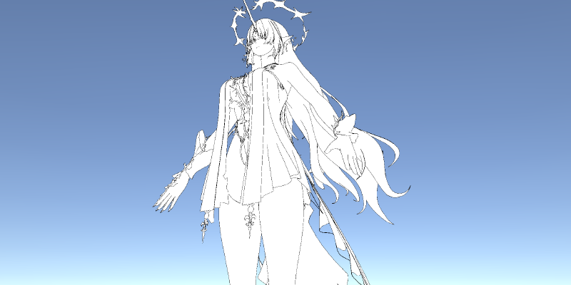
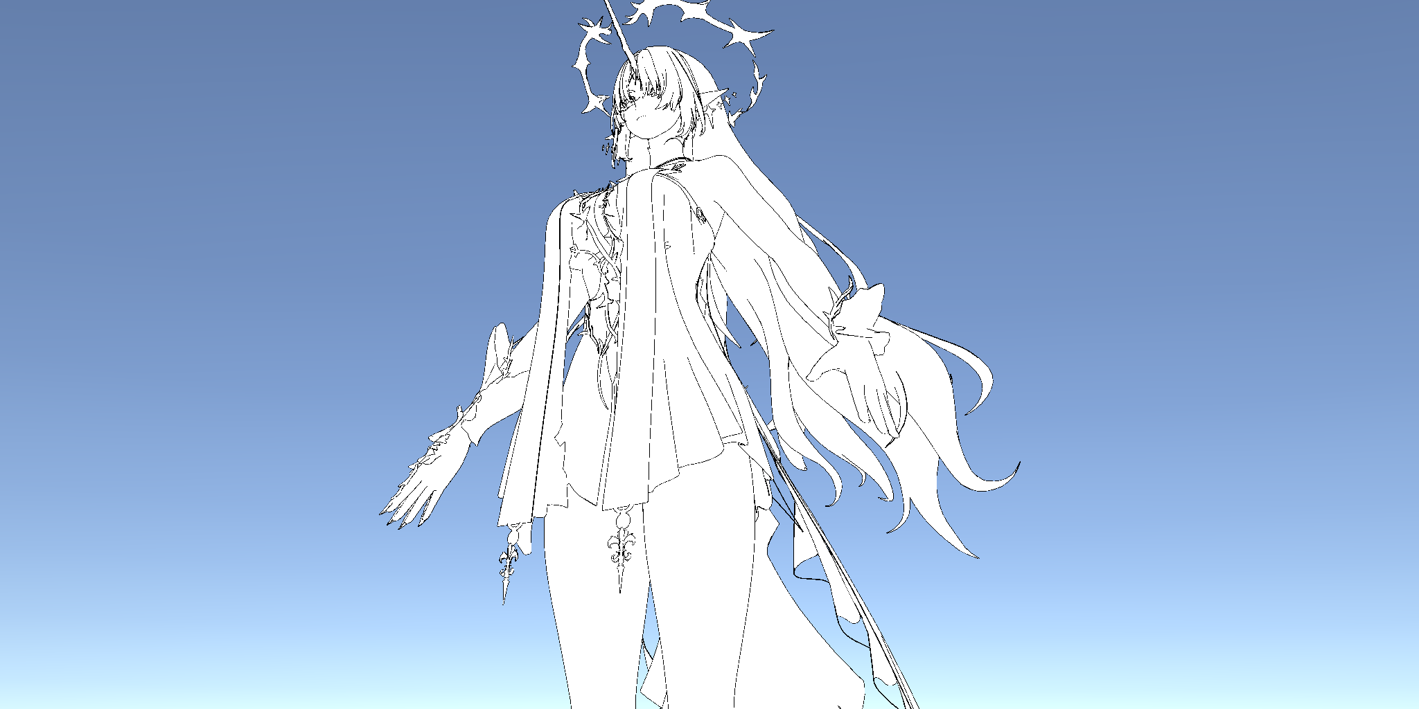
我们用模之屋上IcePaper提供的芙露德莉斯模型来看一下是否使用平均法线的区别(参数都相同的情况下)

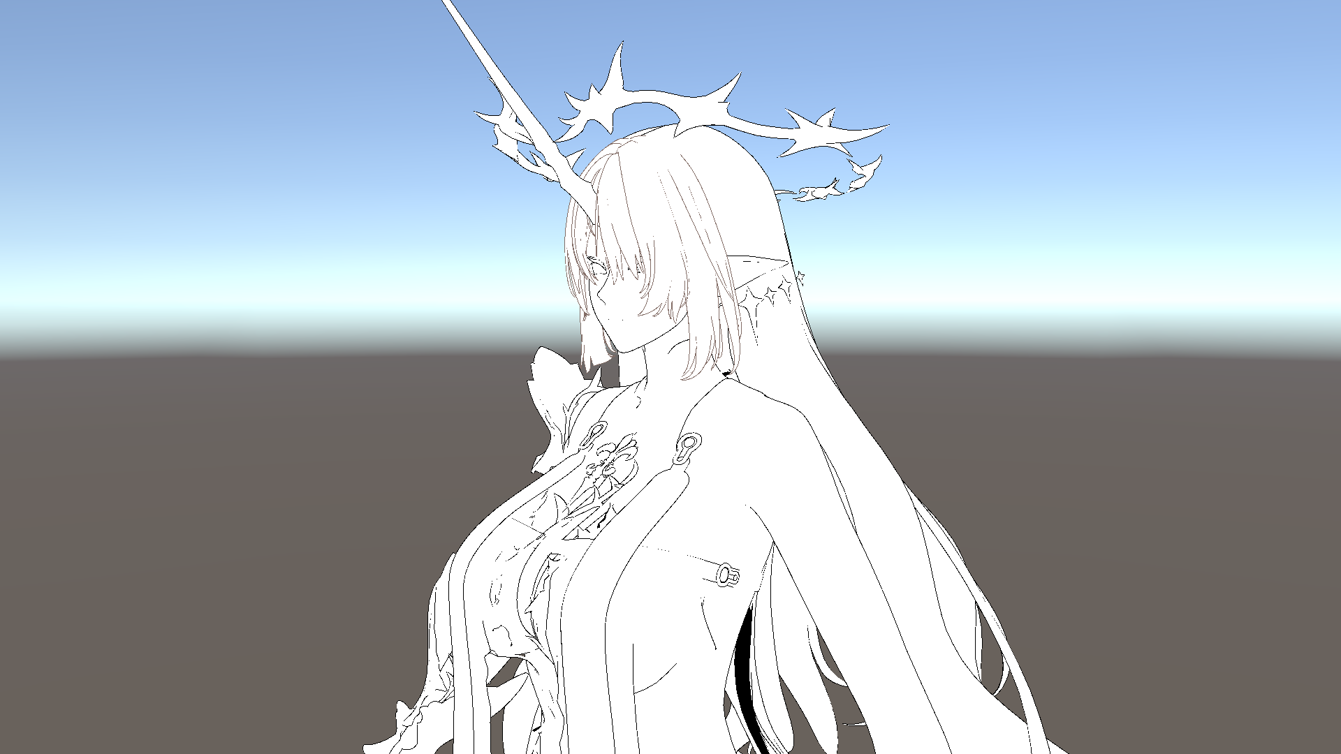
不难发现,细节上存在明显的区别。
需要注意的是,对于Skinned Mesh,其顶点坐标、法线以及切线都是受骨骼动画影响的,又由于自带的法线与切线通常是必要的,因此我们一般用两种方案来处理平均法线:
- 和我们项目里用的类似,使用StructuredBuffer或是GraphicsBuffer,然后自行实现GPU蒙皮并计算实时的平均法线方向。个人推荐这种,因为这种方案灵活性更高,对其他效果支持也更方便。
- 另一种则用的是类似法线贴图的方法,我们计算出平均法线后,利用自带的法线、切线、副法线构成的切空间得到其坐标,然后存到顶点色或是别的UV通道里。在VS里利用蒙皮后的法线与切线重建切空间,重新算出平均法线的方向。
方案局限性
性能差
尽管Early Z似乎能在一定程度上减少多Pass描边的开销,但是仍会有大量无效的片元在光栅化阶段生成。而且通常描边的PS是不复杂的,很多可能人用的和我们演示的一样,就返回预设的描边颜色,没有别的采样。因此我们几乎可以认为,这是100%overdraw的。从性能优化上来说,这是一个非常糟糕的方案。
Blend Shape描边可能的异常
Blend Shape的原理是通过对少量顶点(组)进行插值,从而实现网格连续变化的过程。所以通常Blend Shape只记录那些发生变化的顶点的位置信息,有些做的好一点的也会记录法线信息,但一般都不会再记录切线信息,因此不论我们用哪种方式记录修复的平均法线,都会因为信息的不全而产生失真,从而带来可能的错误描边。
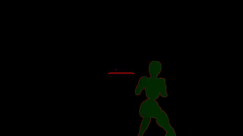
单面边缘描边无效
我们先来看铃芽之旅中的一幕,可以看到铃芽的校服袖子处是存在描边的

而下图(素材来源[2])框中的袖子的边界却并没有描边
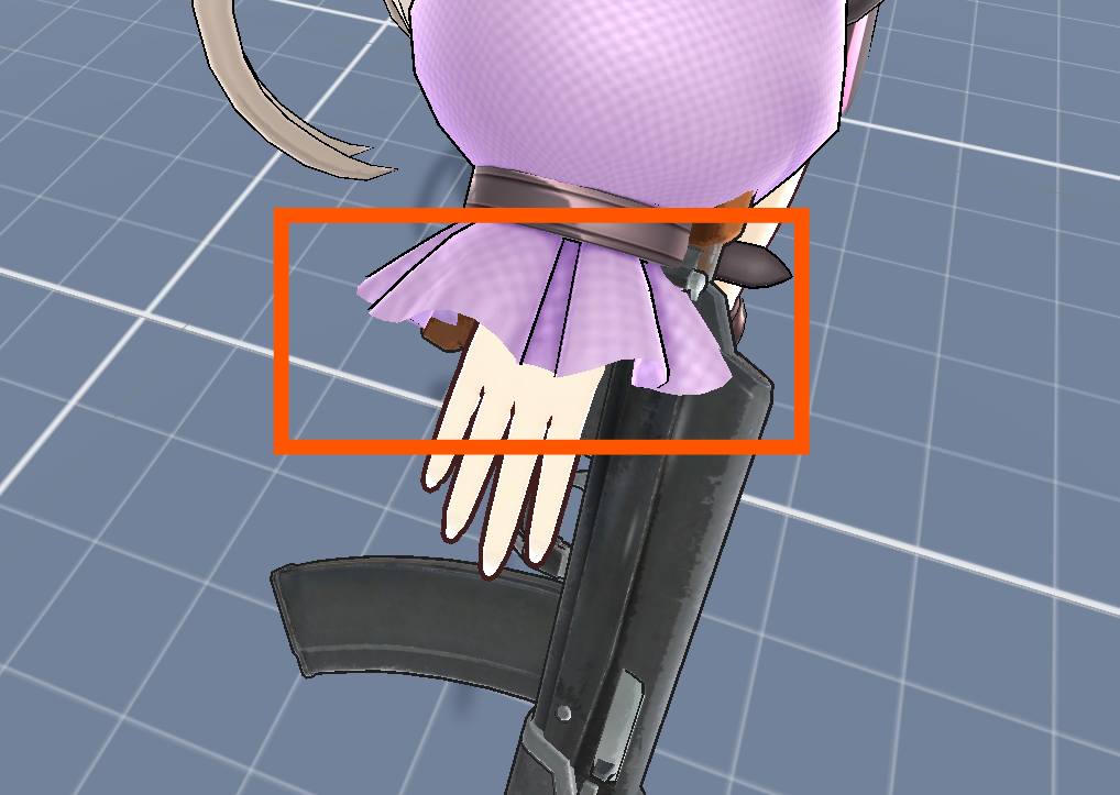
粗略的分析,似乎是因为边界处法线仍然是垂直表面的而不是垂直于法线朝"外"的。那么我们通过下面的方式修改平均法线,使其在边缘处朝"外"
  1
  2
  3
  4
  5
  6
  7
  8
  9
 10
 11
 12
 13
 14
 15
 16
 17
 18
 19
 20
 21
 22
 23
 24
 25
 26
 27
 28
 29
 30
 31
 32
 33
 34
 35
 36
 37
 38
 39
 40
 41
 42
 43
 44
 45
 46
 47
 48
 49
 50
 51
 52
 53
 54
 55
 56
 57
 58
 59
 60
 61
 62
 63
 64
 65
 66
 67
 68
 69
 70
 71
 72
 73
 74
 75
 76
 77
 78
 79
 80
 81
 82
 83
 84
 85
 86
 87
 88
 89
 90
 91
 92
 93
 94
 95
 96
 97
 98
 99
100
101
102
103
104
105
106
107
108
109
110
111
112
113
114
115
116
117
118
119
120
121
122
123
124
125
| private static void AddEdgeTriangle(ref Dictionary<GeoEdge, List<int>> edgeCounter, GeoPoint p0, GeoPoint p1, int tri)
{
var edge = new GeoEdge(p0, p1);
if (edgeCounter.ContainsKey(edge))
{
edgeCounter[edge].Add(tri);
}
else
{
edgeCounter.Add(edge, new List<int>() { tri });
}
}
/// <summary>
/// 获得边界上的点: 如果一条边不被两个三角形共享,那么其顶点就是边界上的点
/// </summary>
/// <param name="triangles"></param>
/// <param name="vertices"></param>
/// <returns></returns>
private static Dictionary<GeoPoint, List<GeoEdge>> GetBoundaryGeoPoints(int[] triangles, Vector3[] vertices, out Dictionary<GeoEdge, List<int>> edgeCounter)
{
edgeCounter = new Dictionary<GeoEdge, List<int>>();//list中记录三角形索引
//
int trianglesCount = triangles.Length / 3;
for (int i = 0; i < trianglesCount; i++)
{
int v0 = triangles[i * 3];
int v1 = triangles[i * 3 + 1];
int v2 = triangles[i * 3 + 2];
//
var p0 = new GeoPoint(vertices[v0]);
var p1 = new GeoPoint(vertices[v1]);
var p2 = new GeoPoint(vertices[v2]);
//
AddEdgeTriangle(ref edgeCounter, p0, p1, i);
AddEdgeTriangle(ref edgeCounter, p1, p2, i);
AddEdgeTriangle(ref edgeCounter, p2, p0, i);
}
//
var boundaryPoints = new Dictionary<GeoPoint, List<GeoEdge>>();
//
foreach (var edge in edgeCounter)
{
if (edge.Value.Count == 1)
{
if (boundaryPoints.ContainsKey(edge.Key.v0))
{
boundaryPoints[edge.Key.v0].Add(edge.Key);
}
else
{
List<GeoEdge> edges = new List<GeoEdge>();
edges.Add(edge.Key);
boundaryPoints.Add(edge.Key.v0, edges);
}
//
if (boundaryPoints.ContainsKey(edge.Key.v1))
{
boundaryPoints[edge.Key.v1].Add(edge.Key);
}
else
{
List<GeoEdge> edges = new List<GeoEdge>();
edges.Add(edge.Key);
boundaryPoints.Add(edge.Key.v1, edges);
}
}
}
//
return boundaryPoints;
}
public static Vector3[] GetBoundaryFixedAvgNormal(int[] triangles, Vector3[] vertices, Vector3[] ns)
{
var boundaryPoints = GetBoundaryGeoPoints(triangles, vertices, out Dictionary<GeoEdge, List<int>> edgeCounter);
//
Vector3[] normals = new Vector3[vertices.Length];
//
Dictionary<GeoPoint, List<int>> vertTriDict = new Dictionary<GeoPoint, List<int>>();
for (int i = 0; i < vertices.Length; i++)
{
GeoPoint geoPoint = new GeoPoint(vertices[i]);
if (!vertTriDict.ContainsKey(geoPoint))
{
vertTriDict[geoPoint] = new List<int>();
}
vertTriDict[geoPoint].Add(i);
}
//
foreach (var vt in vertTriDict)
{
Vector3 sumNormal = Vector3.zero;
List<int> indices = vt.Value;
//
if (boundaryPoints.ContainsKey(vt.Key))
{
//需要计算边界点
var edges = boundaryPoints[vt.Key];
//注意, 边的方向叉乘包含该边的三角形的法线, 就是垂直该边且指向外侧的的方向
//我们只需累加这样的方向
foreach (var edge in edges)
{
int triIndex = edgeCounter[edge][0];//这里肯定有且只有一个三角形符合
Vector3 triNormal = ns[triangles[triIndex * 3]];
Vector3 edgeDir = (edge.v1.Pos - edge.v0.Pos).normalized;
//
sumNormal += Vector3.Cross(edgeDir, triNormal);
}
}
else
{
foreach (int index in indices)
{
sumNormal += ns[index];
}
}
//
foreach (int index in indices)
{
normals[index] = sumNormal.normalized;
}
}
//
return normals;
}
|
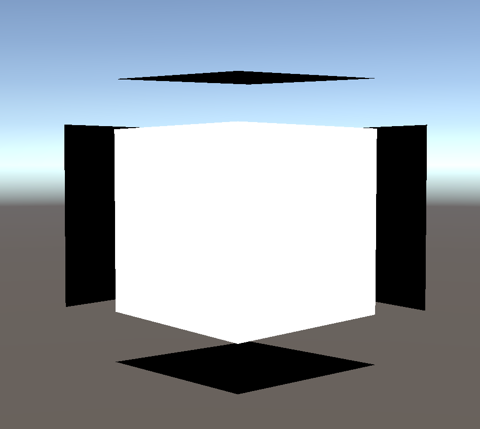
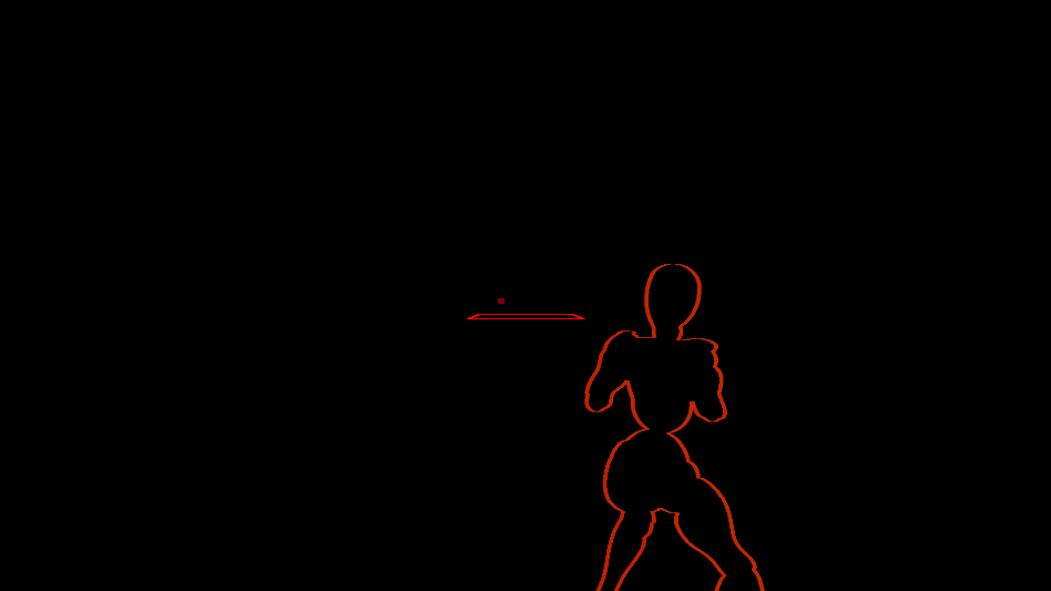
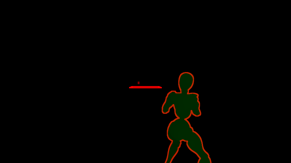
我们用Quad实验一下,看看修正完的"法线"数据是否正确
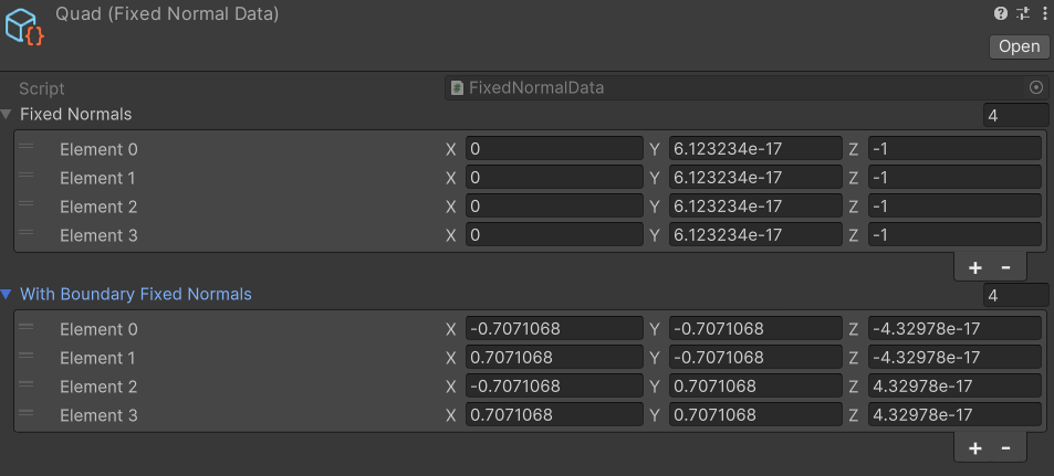
不难看出,确实是垂直于三角形的法线朝"外"的。但很可惜,用这样的法线去给Quad描边,仍然是没有描边效果的。其根本原因是多Pass描边是靠正反两面的差异得到的结果,这在只有单面时就失效了。
那么多Pass描边下,一般是怎么解决这个问题的呢?我看不少游戏的解决方案就是在纹理中加描边。
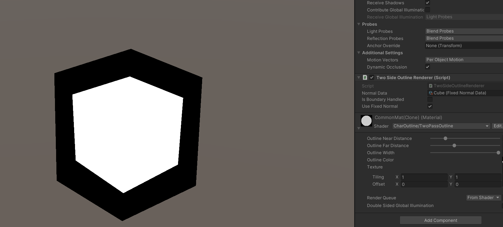
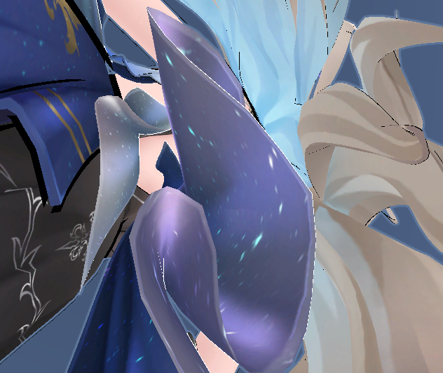
复杂网格描边失效
同样是用芙露德莉斯,我们把描边换为白色,然后调到特殊的视角可以看到

究其原因是这里网格靠的太近了,导致外扩的面穿模了
透明物体描边效果差
并不是说透明物体就无法用多Pass描边来实现描边了,像崩铁的头发的描边就是正常的。不过这种透明本身也需要Stencil Buffer加多Pass来实现,对于复杂一些的物体就很容易产生问题了。
后处理描边
后处理描边一般分两大类,一类是基于边缘检测实现的对场景的描边,一类是对Mask提取边缘并描边。
边缘检测
游戏中的边缘检测一般是利用深度图或是法线图(法线通道),对纹素的邻域检测梯度,来识别物体轮廓。其中最常见的就是用Sobel算子来实现边缘检测。以下面的"法线图"为例,
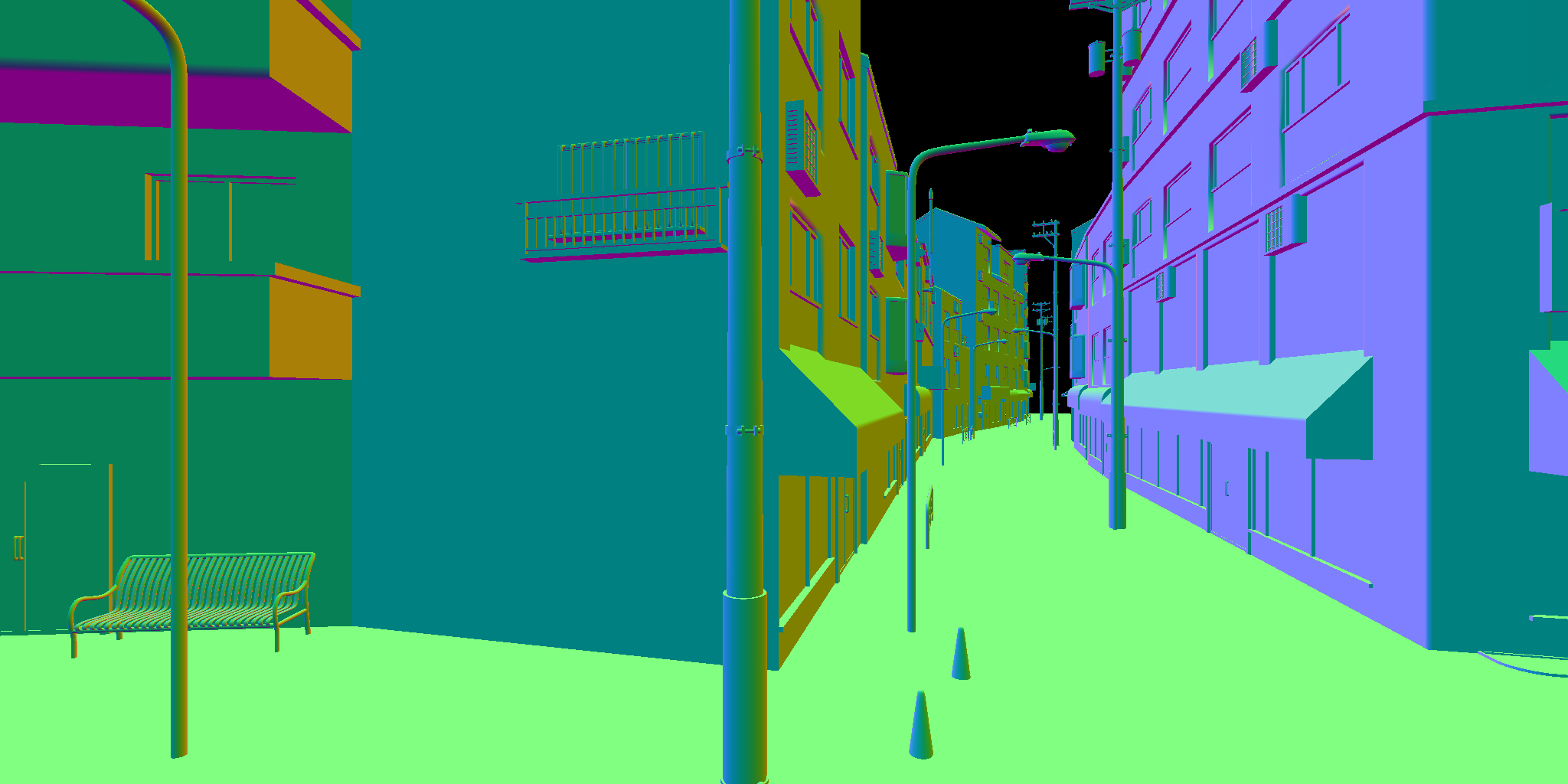
由于Sobel算子需要采样像素的3x3邻域,因此我们宁可浪费一些线程也要用group shared memory来减少重复采样。
 1
 2
 3
 4
 5
 6
 7
 8
 9
10
11
12
13
14
15
16
17
18
19
20
21
22
23
24
25
26
27
28
29
30
31
32
| groupshared float gsSFCols[100];//10x10
//we need to sample 10x10 block's pixels for a 8x8 block's neighbor
//for (8, 8, 1) thread groups, we might encounter scenarios where certain threads require sampling up to 4 times or more,
//or sampling schemes with lower L2 cache hit rates are used.
//in contrast, we adopt a thread group of (10, 10, 1) configuration,
//trading marginal wavefront inefficiency to reduce overheads from sampling (synchronization required for the final thread group) and branch divergence.
[numthreads(10, 10, 1)]
void SobelFilterEdgeDetectKernel (uint3 id : SV_GroupID, uint gindex : SV_GroupIndex, uint3 gid : SV_GroupThreadID)
{
int2 coord = clamp(gid.xy + id.xy * 8 - 1, 0, _InputTexSize - 1);
int2 oCoord = clamp(gid.xy + id.xy * 8, 0, _InputTexSize - 1);
gsSFCols[gindex] = dot(InputTex[coord].xyz, float3(0.222, 0.707, 0.071));
GroupMemoryBarrierWithGroupSync();
//
if (all(gid.xy < 8))
{
float TLCol = GetSobelFilterNeighborCol(gid.xy, int2(-1, 1));
float TCCol = GetSobelFilterNeighborCol(gid.xy, int2(0, 1));
float TRCol = GetSobelFilterNeighborCol(gid.xy, int2(1, 1));
float MLCol = GetSobelFilterNeighborCol(gid.xy, int2(-1, 0));
float MRCol = GetSobelFilterNeighborCol(gid.xy, int2(1, 0));
float BLCol = GetSobelFilterNeighborCol(gid.xy, int2(-1, -1));
float BCCol = GetSobelFilterNeighborCol(gid.xy, int2(0, -1));
float BRCol = GetSobelFilterNeighborCol(gid.xy, int2(1, -1));
//
float G_x = -TLCol + TRCol - 2 * MLCol + 2 * MRCol - BLCol + BRCol;
float G_y = -TLCol - 2 * TCCol - TRCol + BLCol + 2 * BCCol + BRCol;
//RW_OutputGradientTex[oCoord] = float2(G_x, G_y);
RW_OutputTex[oCoord] = float4(length(float2(G_x, G_y)).xxx, 1);
}
}
|
当然,需要注意CPU端分配的线程组大小
1
2
3
| cs.GetKernelThreadGroupSizes(kernelIndex, out uint x, out uint y, out uint z);
//...
cmd.DispatchCompute(cs, kernelIndex, Mathf.CeilToInt(TexWidth / ((float)x - 2)), Mathf.CeilToInt(TexHeight / ((float)y - 2)), 1);
|
于是我们可以得到
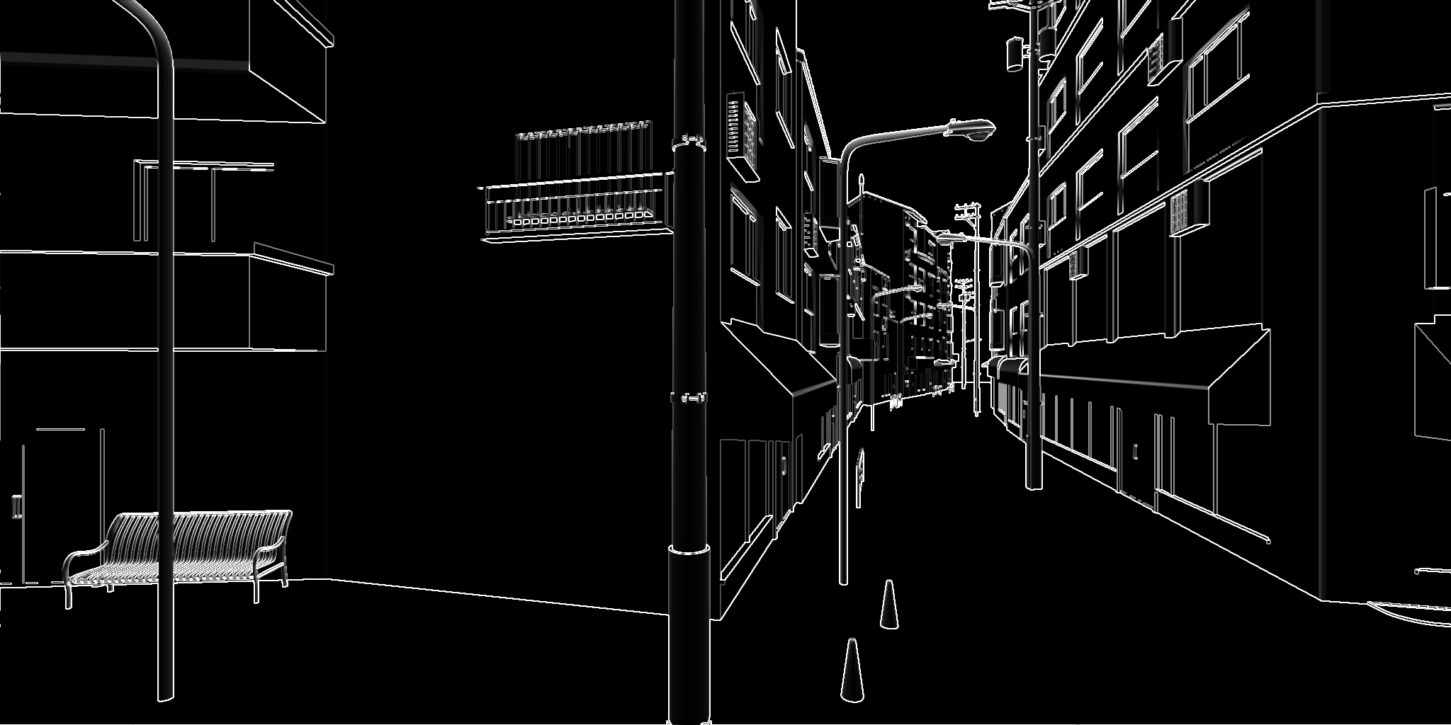
NOTE
我们知道,一个Warp通常是包含32个线程的(我们还是以N卡为主),那么100个线程实际上需要4个Warp来执行,且会存在一个Warp中的线程利用率极低。而这100个线程组,实际需要后续L1缓存访问的也只有64%,剩余36个线程也处于等待状态,因此我不能保证我们这里设定的线程组的大小就是最优解。想要获得最优解需要对不同的硬件以及不同的线程组大小实测才行。
我个人分析边缘的时候更喜欢用利用下面这种更小的邻域(用于其他效果分析时),我们用Gather()类方法来加速,
 1
 2
 3
 4
 5
 6
 7
 8
 9
10
11
12
13
14
15
16
17
18
19
| [numthreads(8, 8, 1)]
void NearestNeighborNormalEdgeDetectKernel (uint3 id : SV_DispatchThreadID)
{
float2 uv = (clamp(id.xy, 0, (uint2)_TexSize.xy) + 0.5) * _TexSize.zw;
//note that using 3 times Gather() is a bit faster than 4 times SampleLevel(),
//gather order: https://learn.microsoft.com/en-us/windows/win32/direct3dhlsl/gather4--sm5---asm-
//0, 1 x, y
//3, 2 w, z
float4 nr = InputTex.GatherRed(sampler_PointClamp, uv);
float4 ng = InputTex.GatherGreen(sampler_PointClamp, uv);
float4 nb = InputTex.GatherBlue(sampler_PointClamp, uv);
//
float3 nR = normalize(cross(float3(-0.5, nr.x - nr.z, 0.5), float3(0.5, nr.y - nr.w, 0.5)));
float3 nG = normalize(cross(float3(-0.5, ng.x - ng.z, 0.5), float3(0.5, ng.y - ng.w, 0.5)));
float3 nB = normalize(cross(float3(-0.5, nb.x - nb.z, 0.5), float3(0.5, nb.y - nb.w, 0.5)));
//
float a = max(1 - nR.y, max(1 - nG.y, 1 - nB.y));
RW_OutputTex[id.xy] = float4(a.xxx, 1);
}
|
将结果增强10倍可得
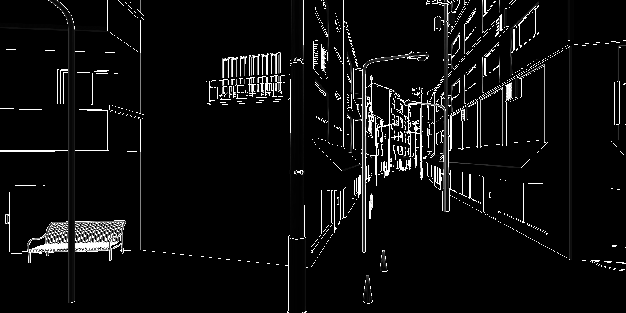
可以看到后者的边缘更细,并且边缘更容易出现(对比左起1/5处的墙间的边缘线)。
Mask描边
很多时候,我们可能只需要对Mask的外边缘描边,而不需要内部描边,并且还可能需要描边保留Mask中绘制了的区域的值的信息,以用于查找最终绘制的颜色。像Need For Speed: Unbound里,车辆加速时的外描边效果就可以通过这种方式来实现。以下面的Mask为例,
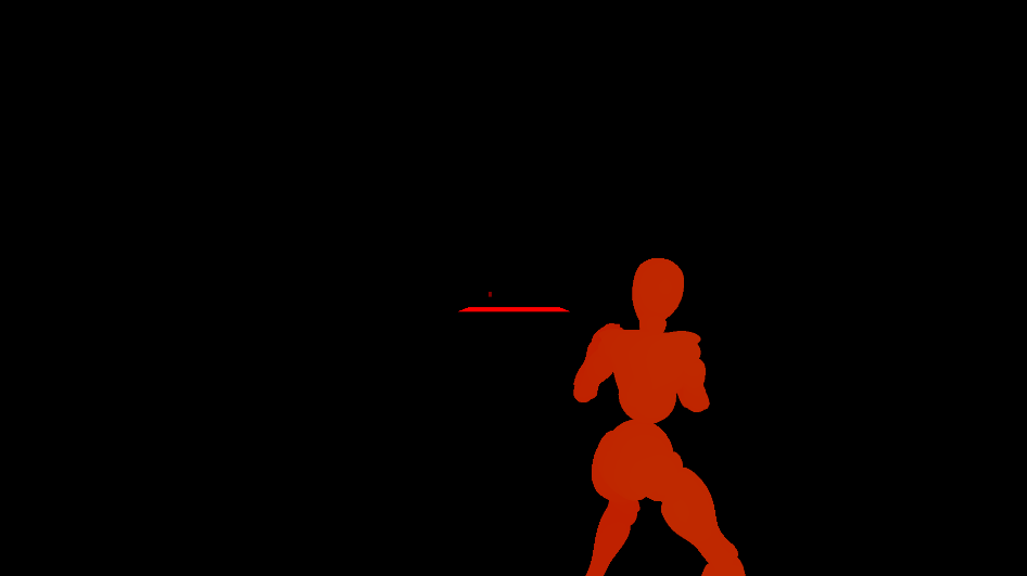
我们首先利用Mask找出边缘(注意, 我们的Mask的y也存了深度信息,为了处理重叠时该用哪一个的情况)
 1
 2
 3
 4
 5
 6
 7
 8
 9
10
11
12
13
14
15
| [numthreads(8, 8, 1)]
void PostProcessEffectOutlineDetectKernel (uint3 id : SV_DispatchThreadID)
{
float2 uv = saturate((_FullScreenTexSize.zw * (id.xy + 0.5)));
//
float2 col = _EffectOutlineMask_RT.SampleLevel(sampler_PointClamp, uv, 0);
float4 nCol = _EffectOutlineMask_RT.GatherRed(sampler_LinearClamp, uv, 0);
float4 nDepth = _EffectOutlineMask_RT.GatherGreen(sampler_LinearClamp, uv, 0);
float2 nMaxCol = float2(nCol.x, nDepth.x);
nMaxCol = lerp(nMaxCol, float2(nCol.y, nDepth.y), step(nMaxCol.y, nDepth.y));
nMaxCol = lerp(nMaxCol, float2(nCol.z, nDepth.z), step(nMaxCol.y, nDepth.z));
nMaxCol = lerp(nMaxCol, float2(nCol.w, nDepth.w), step(nMaxCol.y, nDepth.w));
float3 nColEqualChecker = nCol.xyz - nCol.yzw;
RW_EffectOutlineZone_RT[id.xy] = dot(nColEqualChecker, nColEqualChecker) > 0 ? nMaxCol : float2(0, col.y);//a fast way to check if x,y,z,w components are equal(while, GatherCmpRed() may be faster to check)
}
|
然后就用和Gaussian模糊类似的水平与垂直的两个Kernel将描边信息外扩
 1
 2
 3
 4
 5
 6
 7
 8
 9
10
11
12
13
14
15
16
17
18
19
20
21
22
23
24
25
26
27
28
29
30
31
32
33
34
35
36
37
38
39
40
41
42
43
44
45
46
47
48
49
50
51
52
53
|
#define HALF_THICKSIZE 3
groupshared float2 gsCol[64 + 2 * HALF_THICKSIZE];

[numthreads(64, 1, 1)]
void PostProcessEffectOutlineThickerHorizontalKernel (uint3 id : SV_DispatchThreadID, uint gIndex : SV_GroupIndex)
{
	float2 uv = saturate((_FullScreenTexSize.zw * (id.xy + 0.5)));
	gsCol[gIndex + HALF_THICKSIZE] = _EffectOutlineZone_RT.SampleLevel(sampler_LinearClamp, uv, 0);
	if (gIndex < HALF_THICKSIZE)
	{
		gsCol[gIndex] = _EffectOutlineZone_RT.SampleLevel(sampler_LinearClamp, saturate((_FullScreenTexSize.zw * (id.xy - float2(HALF_THICKSIZE, 0) + 0.5))), 0);
	}
	if (gIndex >= 64 - HALF_THICKSIZE)
	{
		gsCol[gIndex + HALF_THICKSIZE * 2] = _EffectOutlineZone_RT.SampleLevel(sampler_LinearClamp, saturate((_FullScreenTexSize.zw * (id.xy + float2(HALF_THICKSIZE, 0) + 0.5))), 0);
	}
	//
	GroupMemoryBarrierWithGroupSync();
	float2 nMaxCol = 0;
	for (int i = -HALF_THICKSIZE; i <= HALF_THICKSIZE; i++)
	{
		float2 tNCol = gsCol[HALF_THICKSIZE + i + gIndex];
		nMaxCol = tNCol.x > 0 ? lerp(nMaxCol, tNCol, step(nMaxCol.y, tNCol.y)) : nMaxCol;
	}
	RW_EffectOutlineTemp_RT[id.xy] = nMaxCol;
}

[numthreads(1, 64, 1)]
void PostProcessEffectOutlineThickerVerticalKernel (uint3 id : SV_DispatchThreadID, uint gIndex : SV_GroupIndex)
{
	float2 uv = saturate((_FullScreenTexSize.zw * (id.xy + 0.5)));
	gsCol[gIndex + HALF_THICKSIZE] = _EffectOutlineTemp_RT.SampleLevel(sampler_LinearClamp, uv, 0);
	if (gIndex < HALF_THICKSIZE)
	{
		gsCol[gIndex] = _EffectOutlineTemp_RT.SampleLevel(sampler_LinearClamp, saturate((_FullScreenTexSize.zw * (id.xy - float2(0, HALF_THICKSIZE) + 0.5))), 0);
	}
	if (gIndex >= 64 - HALF_THICKSIZE)
	{
		gsCol[gIndex + HALF_THICKSIZE * 2] = _EffectOutlineTemp_RT.SampleLevel(sampler_LinearClamp, saturate((_FullScreenTexSize.zw * (id.xy + float2(0, HALF_THICKSIZE) + 0.5))), 0);
	}
	//
	GroupMemoryBarrierWithGroupSync();
	float2 nMaxCol = 0;
	for (int i = -HALF_THICKSIZE; i <= HALF_THICKSIZE; i++)
	{
		float2 tNCol = gsCol[HALF_THICKSIZE + i + gIndex];
		nMaxCol = tNCol.x > 0 ? lerp(nMaxCol, tNCol, step(nMaxCol.y, tNCol.y)) : nMaxCol;
	}
	//
	float2 col = _EffectOutlineMask_RT.SampleLevel(sampler_PointClamp, uv, 0);
	RW_EffectOutlineZone_RT[id.xy] = nMaxCol.x > 0 ? nMaxCol : float2(0, col.y);
}
|
可以看到得到的描边区域还是比较均匀的。
方案局限性
不像其他两种方案,屏幕空间的描边很难自由控制局部描边宽度,因此我们通常只能将其用于场景的风格化绘制,或是一些VFX,有时也可以用于UI上的VFX。
共享边描边
我忘了最初是在哪里看到这种方案的,印象中说是米哈游在崩三的技术分享中提出的。但说实话,就我自己玩崩三以及米家的游戏经历来看,应该都用的是多(双)Pass描边——都不用抓帧,崩三里相机不止一次"穿模"看到背面的渲染结果了(不知道为什么他们不用这个来做)。所谓共享边本质上就是两个相邻三角形共用的那条边(注意,这里是几何上的——顶点位置一样的),对于网格边界,那些没有相邻的边也将被我们考虑进去。因此,虽然我们叫共享边描边,本质上是找出网格的所有边,只是其中需要利用到共享边的对应的两个三角形的信息罢了。
预计算共享边
其实这个步骤和我们前面提到的计算对边缘修正的平均法线的思路类似,只需要记录每个边的相邻三角形的情况即可。我们序列化且用于后续渲染的共享边的结构如下
 1
 2
 3
 4
 5
 6
 7
 8
 9
10
11
12
13
14
15
16
17
18
19
20
21
22
23
24
25
26
27
28
| [System.Serializable]
public struct OutlineEdge
{
/// <summary>
/// 共享的三角形的数量, 正常就1或2, 因此实际上我们可以和下面的宽度数据压缩为一个, 减少一些带宽
/// </summary>
public int SharedTriCount;
public float EdgeBaseWidth;
//我们按照如下顺序记录顶点索引
//1, 3
//0, 2
public int V0Index;
public int V1Index;
public int V2Index;
public int V3Index;
public OutlineEdge(int sharedTriCount, int v0Index, int v1Index, int v2Index, int v3Index, float edgeBaseWidth = 1)
{
SharedTriCount = sharedTriCount;
EdgeBaseWidth = edgeBaseWidth;
V0Index = v0Index;
V1Index = v1Index;
V2Index = v2Index;
V3Index = v3Index;
}
}
|
计算共享边的方法也很简单
 1
 2
 3
 4
 5
 6
 7
 8
 9
10
11
12
13
14
15
16
17
18
19
20
21
22
23
24
25
26
27
28
29
30
31
32
33
34
35
36
37
38
39
40
41
42
43
44
45
46
47
48
49
50
51
52
53
54
55
56
57
58
59
60
61
62
63
64
65
66
67
68
69
70
71
72
73
74
75
76
77
78
79
80
81
82
83
84
85
86
87
88
89
90
91
92
93
94
95
| private static void AddEdgeTriangle(ref Dictionary<GeoEdge, List<Vector2Int>> edgeCounter, GeoPoint p0, GeoPoint p1, int tri, int offset)
{
var edge = new GeoEdge(p0, p1);
if (edgeCounter.ContainsKey(edge))
{
edgeCounter[edge].Add(new Vector2Int(tri, offset));
}
else
{
edgeCounter.Add(edge, new List<Vector2Int>() { new Vector2Int(tri, offset) });
}
}
private static void GetVerticesIndices(Vector2Int info, int[] triangles, out int v0, out int v1, out int v2, out int v3)
{
int triBaseIndex = info.x * 3;
//
int[] tris = new int[]
{
triangles[triBaseIndex],
triangles[triBaseIndex + 1],
triangles[triBaseIndex + 2]
};
//
v0 = tris[(info.y + 2) % 3];
v1 = tris[info.y];
v2 = tris[(info.y + 1) % 3];
v3 = tris[(info.y + 2) % 3];
}
private static void GetVerticesIndices(Vector2Int t0Info, Vector2Int t1Info, int[] triangles, out int v0, out int v1, out int v2, out int v3)
{
int triBaseIndex = t0Info.x * 3;
//
int[] tris = new int[]
{
triangles[triBaseIndex],
triangles[triBaseIndex + 1],
triangles[triBaseIndex + 2]
};
//
v0 = tris[(t0Info.y + 2) % 3];
v1 = tris[t0Info.y];
v2 = tris[(t0Info.y + 1) % 3];
v3 = triangles[t1Info.x * 3 + ((2 + t1Info.y) % 3)];
}
public static OutlineEdge[] GetOutlineEdges(int[] triangles, Vector3[] vertices)
{
var edgeCounter = new Dictionary<GeoEdge, List<Vector2Int>>();//list中记录三角形索引以及当前边的offset
//
int trianglesCount = triangles.Length / 3;
for (int i = 0; i < trianglesCount; i++)
{
int v0 = triangles[i * 3];
int v1 = triangles[i * 3 + 1];
int v2 = triangles[i * 3 + 2];
//
var p0 = new GeoPoint(vertices[v0]);
var p1 = new GeoPoint(vertices[v1]);
var p2 = new GeoPoint(vertices[v2]);
//
AddEdgeTriangle(ref edgeCounter, p0, p1, i, 0);
AddEdgeTriangle(ref edgeCounter, p1, p2, i, 1);
AddEdgeTriangle(ref edgeCounter, p2, p0, i, 2);
}
//
var outlineEdges = new List<OutlineEdge>();
//
foreach (var ec in edgeCounter)
{
int v0, v1, v2, v3;
var tris = ec.Value;
if (tris.Count < 2)
{
if (tris.Count == 1)
{
Vector2Int tInfo = tris[0];
GetVerticesIndices(tInfo, triangles, out v0, out v1, out v2, out v3);
outlineEdges.Add(new OutlineEdge(1, v0, v1, v2, v3));
}
//如果小于1, 显然是异常的, 直接无视这样的边
}
else
{
Vector2Int t0Info = tris[0];
Vector2Int t1Info = tris[1];
GetVerticesIndices(t0Info, t1Info, triangles, out v0, out v1, out v2, out v3);
outlineEdges.Add(new OutlineEdge(2, v0, v1, v2, v3));
}
}
//
return outlineEdges.ToArray();
}
|
绘制描边
我记得当时看到的教程用的是geometry shader来绘制边,那时候还不懂,现在我肯定是不会去用geometry shader了。我们在CS里分配需要绘制的边,并计算clip space下的坐标,直接给绘制时的VS用。
  1
  2
  3
  4
  5
  6
  7
  8
  9
 10
 11
 12
 13
 14
 15
 16
 17
 18
 19
 20
 21
 22
 23
 24
 25
 26
 27
 28
 29
 30
 31
 32
 33
 34
 35
 36
 37
 38
 39
 40
 41
 42
 43
 44
 45
 46
 47
 48
 49
 50
 51
 52
 53
 54
 55
 56
 57
 58
 59
 60
 61
 62
 63
 64
 65
 66
 67
 68
 69
 70
 71
 72
 73
 74
 75
 76
 77
 78
 79
 80
 81
 82
 83
 84
 85
 86
 87
 88
 89
 90
 91
 92
 93
 94
 95
 96
 97
 98
 99
100
101
102
103
104
105
106
107
108
109
110
111
112
113
114
115
116
117
118
119
120
121
122
123
124
125
126
127
128
129
130
131
132
133
134
135
136
137
138
139
140
141
142
143
144
145
146
147
148
| #define DEPTH_BIAS 0.0001
struct OutlineEdge
{
int SharedTriCount;
float EdgeBaseWidth;
int V0Index;
int V1Index;
int V2Index;
int V3Index;
};
uint _MeshEdgeCount;
uint _VerticesBufferStride;
uint _VerticesBufferOffset;
float _OutlineWidth;
float _OutlineFarDis;
float _OutlineNearDis;
float4x4 _ObjToWorldMatrix;
ByteAddressBuffer _BakedVerticesBuffer; //use SkinnedMeshRenderer.GetVertexBuffer() to get the buffer
StructuredBuffer<OutlineEdge> _MeshOutlineDataBuffer;
RWStructuredBuffer<uint> RW_EdgeArgBuffer;
//note that we should calculate vertices here but not in vs (only need calculate 4 vertex in cs, but need to calculate 6 in vs)
RWStructuredBuffer<float4> RW_ClipSpaceEdgeVerticesBuffer;
[numthreads(1, 1, 1)]
void InitEdgeArgBufferKernel(uint3 id : SV_DispatchThreadID)
{
RW_EdgeArgBuffer[0] = 6; //2 triangle pre instance (3 * 2)
RW_EdgeArgBuffer[1] = 0; //to draw rect count ----Value that we need to count----
RW_EdgeArgBuffer[2] = 0; //start vertex location
RW_EdgeArgBuffer[3] = 0; //start instance location
RW_EdgeArgBuffer[4] = 0; //default value for glsl
}
//ref: https://atyuwen.github.io/posts/antialiased-line/
void AddRectToOutlineSequence(float4 p0, float4 p1, float3 cwp, float baseWidth)
{
if (p0.w > p1.w)
{
float4 temp = p0;
p0 = p1;
p1 = temp;
}
if (p0.w < _ProjectionParams.y)//clamp to frustum
{
float ratio = (_ProjectionParams.y - p0.w) / (p1.w - p0.w);
p0 = lerp(p0, p1, ratio);
}
float2 a = p0.xy / p0.w; //sspos
float2 b = p1.xy / p1.w;
//
float disFactor = smoothstep(_OutlineFarDis, _OutlineNearDis, length(_WorldSpaceCameraPos - cwp));
float2 c = normalize(float2(a.y - b.y, b.x - a.x)) * (_ScreenParams.zw - 1.0) * _OutlineWidth * baseWidth * disFactor;
//add bias to avoid Z-fighting (this cannot completely eliminate the problem)
float4 v0 = float4(p0.xy + c * p0.w, p0.zw + float2(0, DEPTH_BIAS));
float4 v1 = float4(p0.xy - c * p0.w, p0.zw + float2(0, DEPTH_BIAS));
float4 v2 = float4(p1.xy + c * p1.w, p1.zw + float2(0, DEPTH_BIAS));
float4 v3 = float4(p1.xy - c * p1.w, p1.zw + float2(0, DEPTH_BIAS));
//
uint instanceID;
InterlockedAdd(RW_EdgeArgBuffer[1], 1, instanceID);
//
RW_ClipSpaceEdgeVerticesBuffer[instanceID * 6] = v0;
RW_ClipSpaceEdgeVerticesBuffer[instanceID * 6 + 1] = v2;
RW_ClipSpaceEdgeVerticesBuffer[instanceID * 6 + 2] = v1;
RW_ClipSpaceEdgeVerticesBuffer[instanceID * 6 + 3] = v1;
RW_ClipSpaceEdgeVerticesBuffer[instanceID * 6 + 4] = v2;
RW_ClipSpaceEdgeVerticesBuffer[instanceID * 6 + 5] = v3;
}
float4 ObjToHClip(float3 p)
{
return mul(UNITY_MATRIX_VP, mul(_ObjToWorldMatrix, float4(p, 1)));
}
float4 ObjToWorld(float3 p)
{
return mul(_ObjToWorldMatrix, float4(p, 1));
}
float4 WorldToHClip(float4 p)
{
return mul(UNITY_MATRIX_VP, p);
}
float3 LoadVertexData(uint index)
{
uint byteAddress = index * _VerticesBufferStride + _VerticesBufferOffset;
//note that, for newly version of DirectXShaderCompiler, we can load types other than uint directly
//ref: https://github.com/microsoft/DirectXShaderCompiler/wiki/ByteAddressBuffer-Load-Store-Additions
uint3 uPos = _BakedVerticesBuffer.Load3(byteAddress);
return asfloat(uPos);
}
//TODO: use group shared memory as intermediate buffer to add edges
[numthreads(64, 1, 1)]
void DispatchSilhouetteEdges(uint3 id : SV_DispatchThreadID)
{
if (id.x >= _MeshEdgeCount)
{
return;
}
OutlineEdge edge = _MeshOutlineDataBuffer[id.x];
//
if (edge.SharedTriCount == 1)
{
//the edge is border of mesh, hence should be outline
float3 v1 = LoadVertexData(edge.V1Index);
float3 v2 = LoadVertexData(edge.V2Index);
float4 p1 = ObjToWorld(v1);
float4 p2 = ObjToWorld(v2);
//
AddRectToOutlineSequence(WorldToHClip(p1), WorldToHClip(p2), 0.5 * (p1 + p2).xyz, edge.EdgeBaseWidth);
}
else
{
//
float3 v0 = LoadVertexData(edge.V0Index);
float3 v1 = LoadVertexData(edge.V1Index);
float3 v2 = LoadVertexData(edge.V2Index);
float3 v3 = LoadVertexData(edge.V3Index);
//
float4 p0 = ObjToWorld(v0);
float4 p1 = ObjToWorld(v1);
float4 p2 = ObjToWorld(v2);
float4 p3 = ObjToWorld(v3);
//
float3 t0 = (p0 + p1 + p2).xyz / 3;
float3 t1 = (p1 + p2 + p3).xyz / 3;
float3 viewDir0 = normalize(t0 - _WorldSpaceCameraPos);
float3 viewDir1 = normalize(t1 - _WorldSpaceCameraPos);
//
float3 n0 = cross(normalize((p1 - p0).xyz), normalize((p2 - p0).xyz));//normalize for safe
float3 n1 = cross(normalize((p3 - p1).xyz), normalize((p2 - p1).xyz));
//
float c0 = dot(viewDir0, n0);
float c1 = dot(viewDir1, n1);
if (sign(c0) != sign(c1))//silhouette edge
{
//need to be outline
AddRectToOutlineSequence(WorldToHClip(p1), WorldToHClip(p2), 0.5 * (p1 + p2).xyz, edge.EdgeBaseWidth);
}
}
}
|
理论上这应该是共享边绘制的最佳方案了。当然,以上方案正如我注释的那样,还可以用group shared memory作为中间buffer进一步的减少InterlockedAdd的同步开销。
下面我们来说一下为什么不用geometry shader。以DX的API为例,我们需要知道其绘制命令主要有Draw()与DrawIndexed()两大类区别(不考虑indirect以及instanced),这两个接口的最大区别就在于DrawIndexed()会使用(指定的)index buffer而不是顺序处理,这让其真正的使用上了post-transform cache(有时也被称为vertex cache,即,顶点缓存——虽然可能有歧义,但我更喜欢这种叫法)这一特性。这个特性的作用是可以复用VS中处理完的结果(当然,这是少量可以复用),举个例子就是一个Quad由两个三角形6个顶点组成。在用Draw()绘制的时候我们必须提供6个顶点的数据,而用DrawIndexed()则只会计算4个顶点,公共边的两个顶点会直接从缓存中读取。需要注意的是,这和MeshTopology没有任何关系,在unity中,MeshTopology用Quad与用Triangle的区别只在于你自己传入的用于VS中读取的index buffer的带宽变小了,而并不会启用顶点缓存(API文档中也说了,绝大多数GPU中,Quad都是模拟的)。启用顶点缓存时的帧率(unity中启用顶点缓存靠的是需要传入一个索引的GraphicsBuffer的那些接口),差不多是未启用的1.5倍,而仅仅是将MeshTopology的Quad改为Triangle并修改VS中读取顺序的方案,只将帧率提高了1帧左右(33ms提升至34ms),这与我们用Triangle自行手动模拟Quad的方案是一样的。
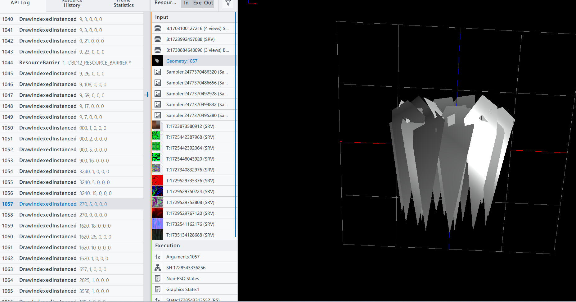
很显然,geometry shader会"破坏"顶点缓存,更别说其他的问题了。这里也不得不吐槽一嘴,我最早接触到geometry shader的时候应该就是绘制草场用geometry shader,我一直不明白,为什么不在传入的模型的顶点中做动画?偏要用geometry shader来实现呢?附一张抓的Horizon Zero Dawn的一帧,用的就是DrawIndexedInstanced()+模型(可以明确只有VS+PS)
未来与展望
关于描边,还有几个未来需要考虑如何更好的实现的内容,算是TODO List,也留些参考
透明物体的描边
透明玻璃杯是最常见的需要描边的透明物体


环境对描边色的影响


References
[1]IcePaper 鸣潮-芙露德莉斯
[2]CombatGirls_RifleCharacterPack
[3]铃芽之旅
[4]Draw Anti-aliased Lines with Geometry Shader
[5]你的名字
[6]Jen 113407548